FM Receiving Antenna


Tip
You will find some NEC lab samples in the Nec Lab folder (C:\Program Files (x86)\Neclab)

Problem 1
A four elements directional antenna to operate in the band from 100 MHz to 108 MHz will be designed. Suppose that the desired impedance is 75 Ohms and that a minimum gain of 6.5 dBd is required. NEC Lab will be used to determine the best positions and lengths of the wires to meet the required goals. Assume that the five elements are initially anywhere in the space XYZ, and that they are paralleled to each other.

antenna

Step 1
  1. Open NEC Lab - this will create an empty project.
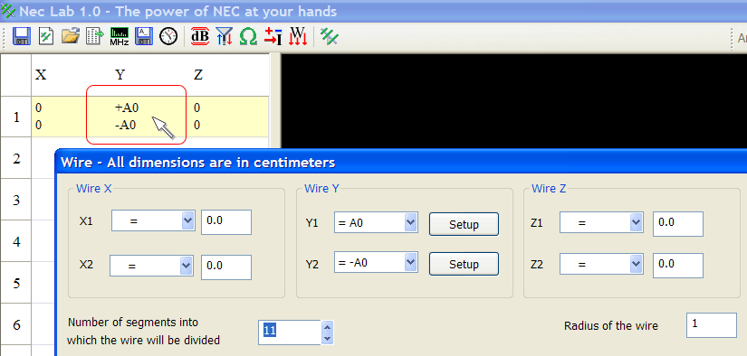
  2. Select the first wire by making double click on the first wire on the left panel. The Wire dialog will be open as shown.

selectWire1

Step 2
The wire dialog allows editing both ends of a wire. For each end there is a 3D coordinate point that can be setup as:
  • a numeric a value
  • a variable, or
  • a value that NEC Lab will optimize
For this example, Wire 1 will be placed at the origin.
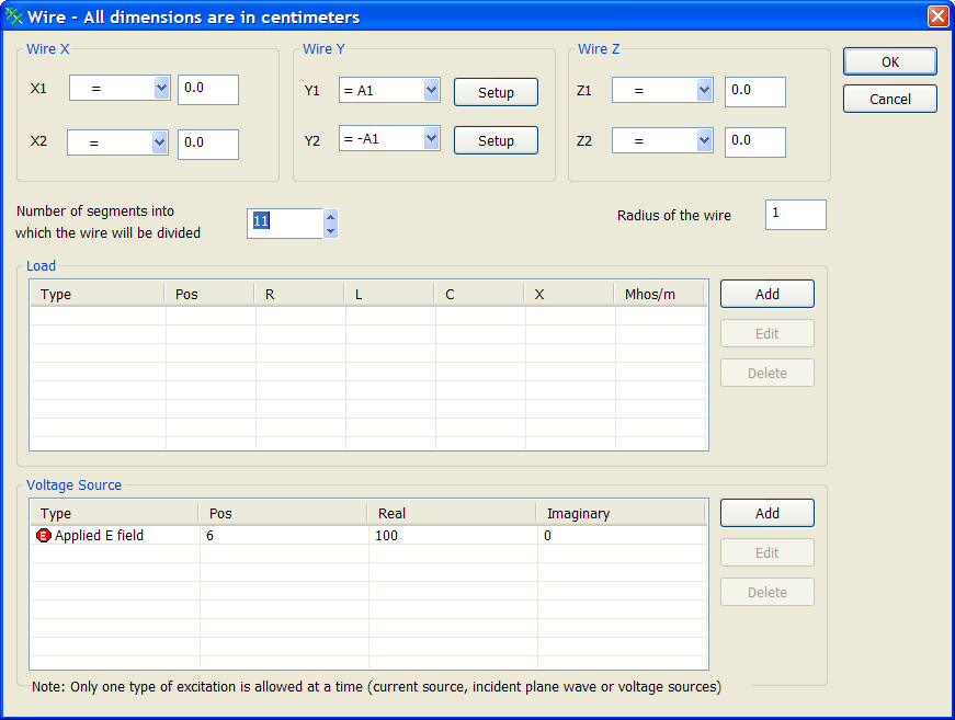
  1. Click on the Drop Down box next to Y1 and set Y1 = A1.
  2. Click on the Drop Down box next to Y2 and set Y2 = -A1.

editWire1

Step 3
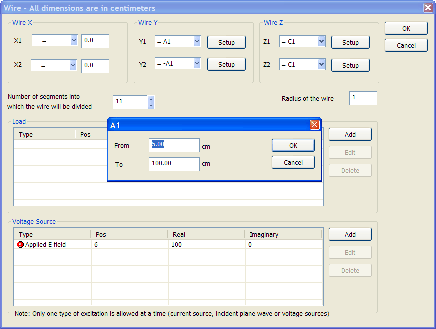
Set the range for A1 and C1
  1. NEC Lab will optimize the value of A1 when running the designer, it will however require a range to create an antenna draft. Click on the Y1 Setup button. A new dialog to edit the possible range for the variable A1 will be open. Verify that the range is as shown. Press OK to close the A1 dialog.
  2. Press OK to close the Wire dialog.

editRangeA1

Step 4. Adding a second wire.
  1. On the toolbar click: Add WireAdd Wire
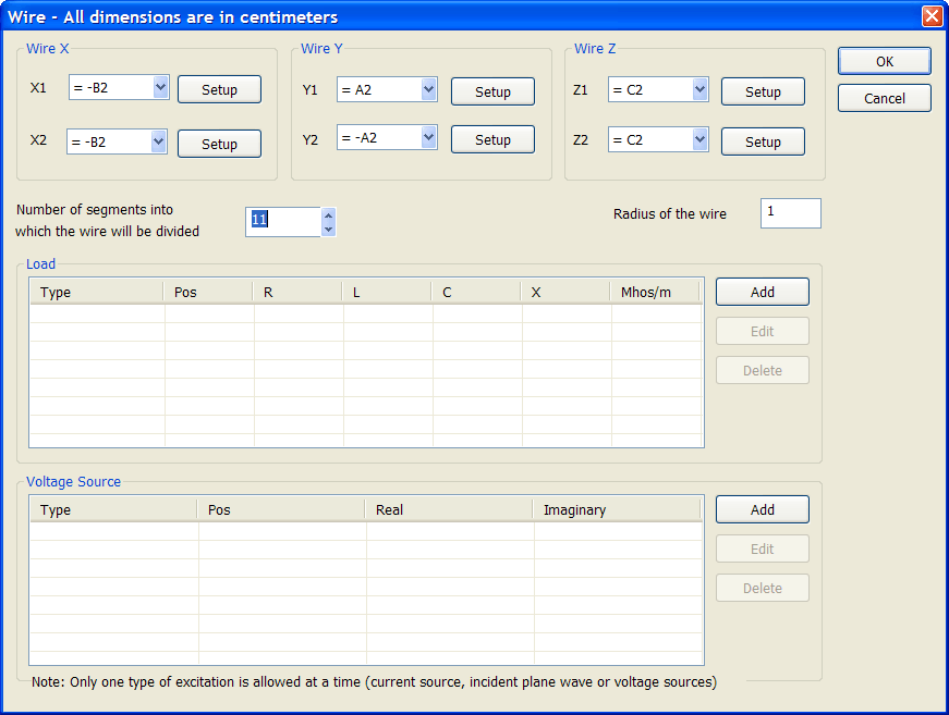
  2. Set  X1= -B2 and  X2 = -B2
  3. Set  Y1 = A2 and  Y2 = -A2
  4. Set  Z1= C2 and  Z2 = C2

editWire2

Step 5
Set the range for A2, B2 and C2.
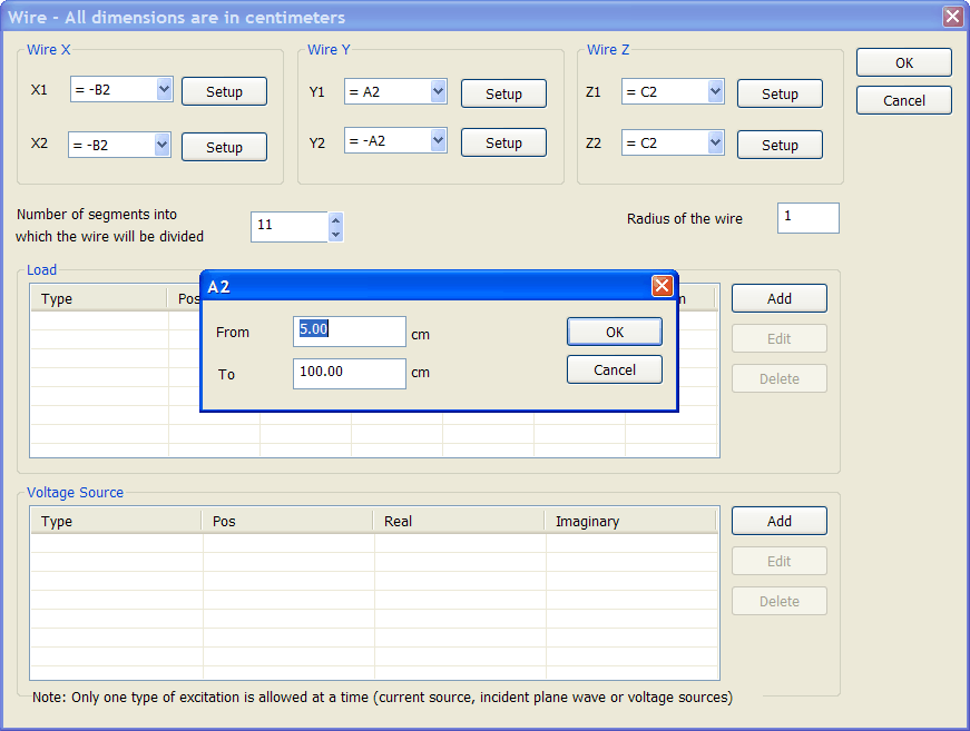
  1. Press the Y1 Setup button and verify that the range of A2 is from 5.00 to 100.00 centimeters
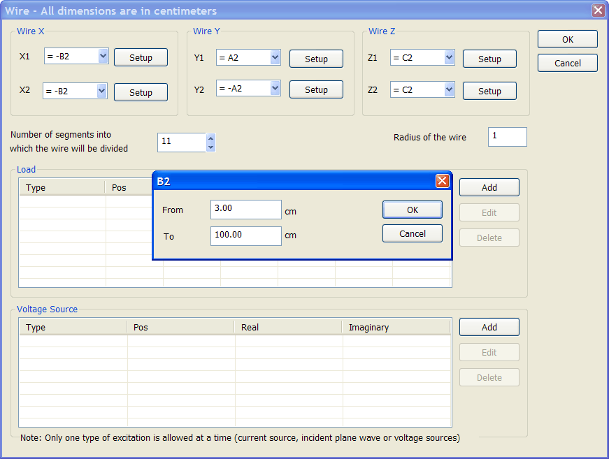
  2. Press the X1 Setup button and set the range of B2 from 3.00 to 100.00 centimeters
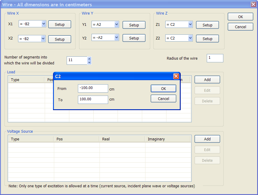
  3. Press the Z1 Setup button and set the range of C2 from -100.00 to 100.00 centimeters

editRangeA2

editRangeB2

editRangeC2

Step 6
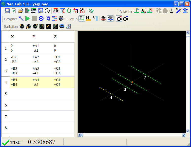
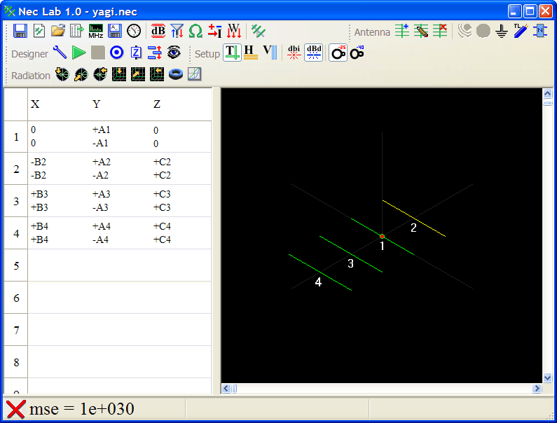
Add wires: 3 and 4. Following the procedure previously described add two more wires as shown:

Wire 3    Range  
X1= +B3 B3 from 3 to 100
X2= +B3      
Y1= +A3A3 from 5 to 100
Y2= -A3      
Z1= C3C3 from -100.00 to 100.00
Z2= C3      

Wire 4    Range  
X1= +B4B4 from 5 to 200
X2= +B4      
Y1= +A4A4 from 5 to 100
Y2= -A4      
Z1= C4C4 from -100.00 to 100.00
Z2= C4      

antenna_setup

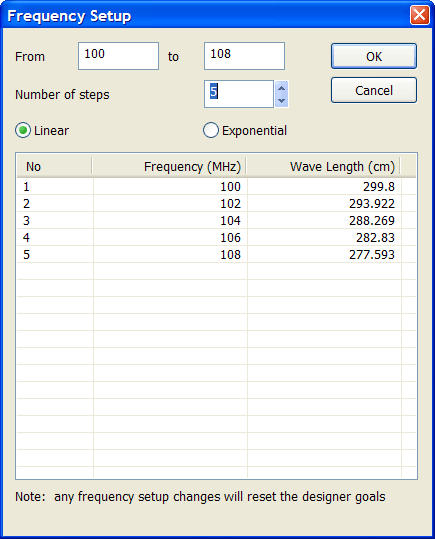
Step 7 Frequency setup.
  1. On the toolbar click: FrequencyFrequency
  2. Set the frequency parameters as shown
  3. Press OK to close the dialog

frequencySetup

Step 8 Impedance setup.
  1. On the toolbar click: Designer Goal ImpedanceDesigner Goal Impedance
  2. Select Z = 75 Ohms
  3. Press OK to close the dialog

ImpedanceSetup

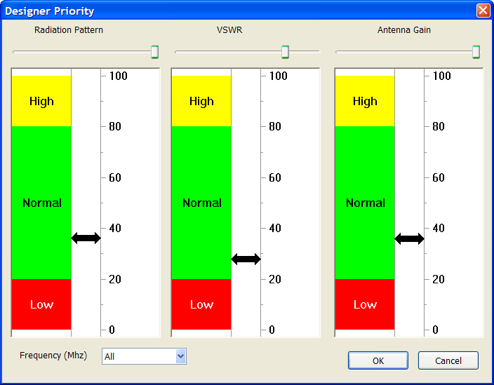
Step 9. Designer Priority Setup.
  1. Designer PriorityDesigner Priority
  2. For a receiving antenna the VSWR is not as important as for a transmitting antenna. Set the priorities as shown.
  3. Press OK to close the dialog

DesignerPrioritySetup

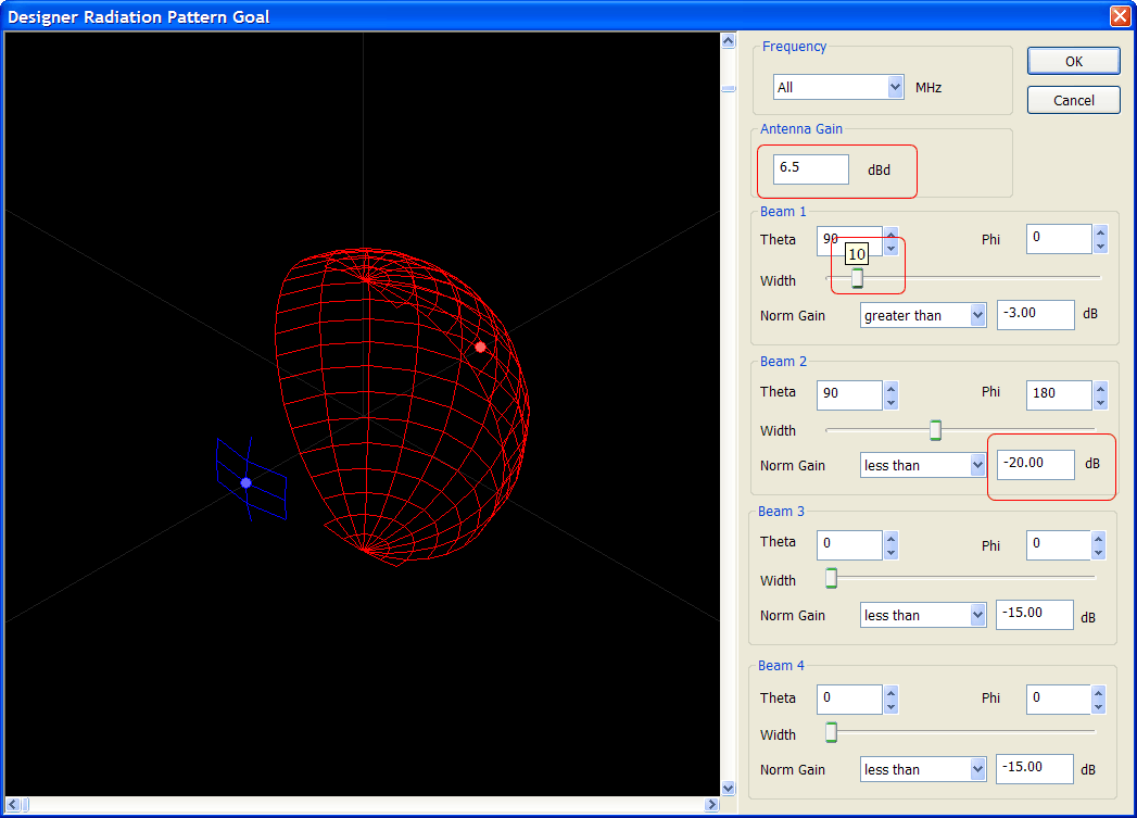
Step 10. Designer Goal Setup.
  1. On the toolbar click: Designer Radiation Pattern GoalDesigner Radiation Pattern Goal
  2. NEC Lab defines the radiation pattern as a set of 3D beams. The radiation pattern of this antenna will be defined using only two beams: beam 1 and beam 2
  3. On the radiation pattern goal dialog change the Antenna Gain to 6.5 dBd as shown
  4. On the radiation pattern goal dialog change the Beam 1 Width to 10 as shown
  5. On the same dialog, change the Normalized Gain of Beam 2: Norm Gain < -20 dB
  6. Press OK to close the dialog

rp_goal

Step 11. Running the Designer.
  1. Once the antenna requirements have been defined, it is a good idea to save the project. On the toolbar click: NEC SaveNEC Save
  2. Select an appropriate folder in your computer and set the filename. Press the Save button to close the dialog.
  3. NEC Lab uses artificial intelligence and is capable of designing a great range of antennas. On the toolbar click: Run the DesignerRun the Designer
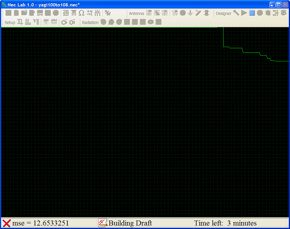
  4. Once the designer is running, NEC Lab will periodically report the mean-squared error measured between the actual antenna performance and the target requirements.
  5. First, the designer will create a draft. Second, the designer will improve the design. Depending on your computer speed and the antenna complexity, the designer may run for one to several hours. NEC Lab will estimate the remaining running time. However, it may stop early, if not further improving is expected.
  6. In some cases and depending on the antenna requirements, the designer will not be able to reach appropriately all the goals. In this case, the mean squared-error of the antenna will not decrease. Consider for example a two element antenna with a requirement of a minimum gain of 8 dBd; with only two elements the designer will not be able to attain the required gain no matter what the lengths or positions of the wires are.

running_designer

Step 12. Analyzing the Results.
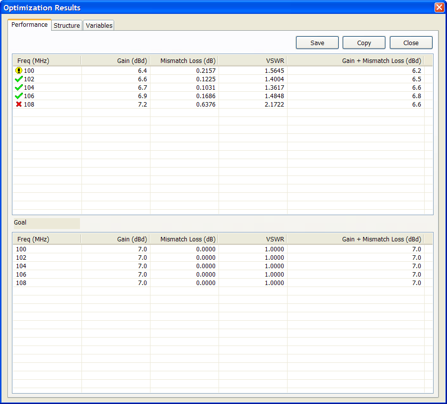
  1. Once the designer stops, the Optimization Results dialog will open. Review the performance antenna. When done press the Close button. You may open this dialog at any time by clicking: Designer ResultsDesigner Results
  2. If the optimizations results are not optimum, you may:
    • run the designer again
    • modify the designer goals, or
    • modify the antenna structure.
  3. Note that it is normal to get different results every time the designer runs. You should try running the designer several times and select the antenna with the best results.
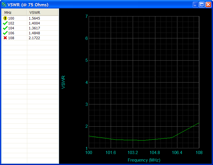
  4. The icon of the left indicates the quality of the VSWR. As expected, the VSWR is not perfect. However, it is acceptable for a receiving antenna. Specifically, the VSWR is a little high for a frequency of 108 MHz.
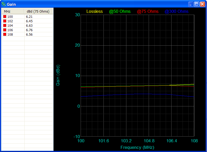
  5. The last column indicates the total gain including any mismatch loss.

results

Step 13. Check the radiation pattern.
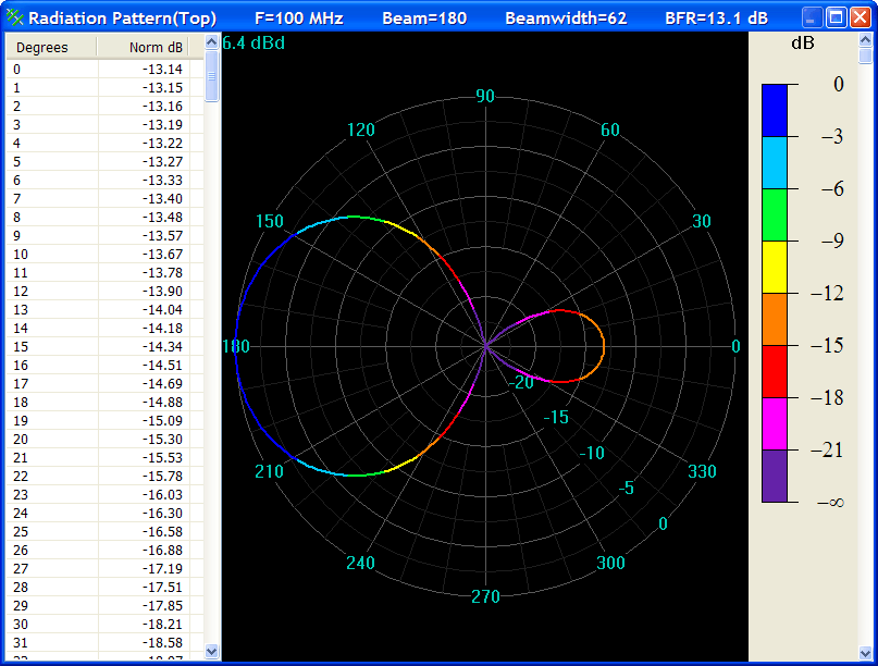
On the toolbar click: Top - Polar Radiation PatternTop - Polar Radiation Pattern
  • Using the right button of the mouse you can export the plot or data to other applications.
  • You may use the rightmost scrollbar to see the radiation of pattern of this antenna at other frequencies.
  • Press OK to close the dialog

  • rp_top

    Step 14. Check the 3D radiation pattern.
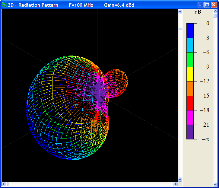
    1. On the toolbar click:3D - Radiation Pattern3D - Radiation Pattern
    2. Using the right button of the mouse you can export the plot or data to other applications.
    3. You may use the rightmost scrollbar to see the radiation of pattern of this antenna at other frequencies.
    4. You may use the other scrollbars to turn and zoom the radiation pattern.
    5. Press OK to close the dialog

    rp_3d

    Step 15. Check the antenna gain.
    1. On the toolbar click: Antenna GainAntenna Gain
    2. Using the right button of the mouse you can export the plot or data to other applications.
    3. Press OK to close the dialog

    gain

    Step 16. Check the antenna VSWR.
    1. On the toolbar click: Antenna VSWRAntenna VSWR
    2. Using the right button of the mouse you can export the plot or data to other applications.
    3. Press OK to close the dialog

    vswr

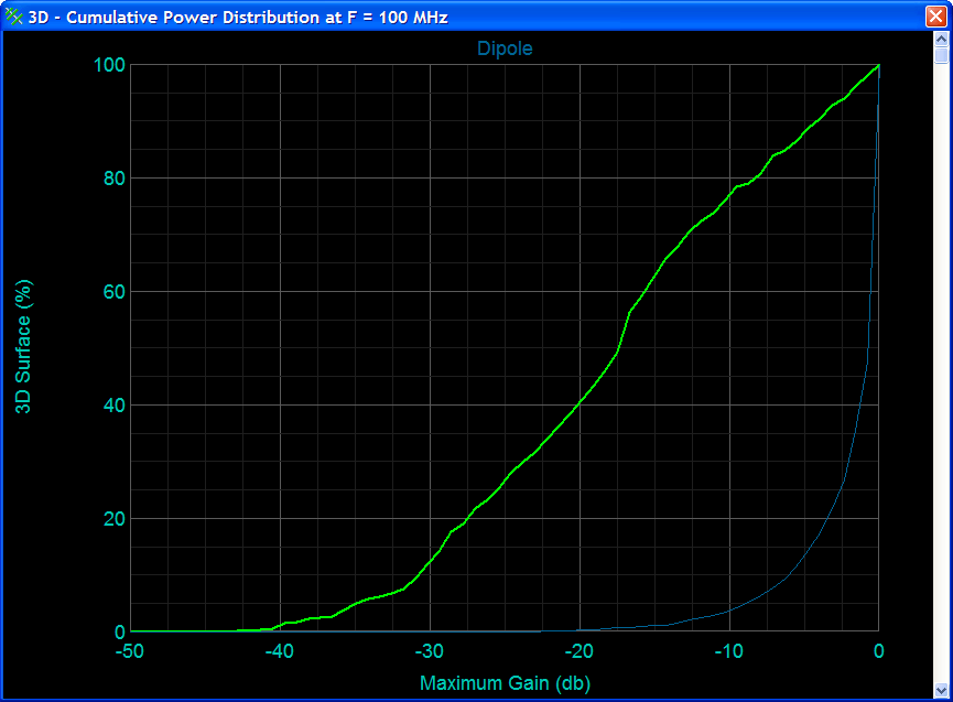
    Step 17. Check the Antenna Power Distribution.
    1. On the toolbar click: 3D - Polar Distribution3D - Polar Distribution
    2. Using the right button of the mouse you can export the plot or data to other applications.
    3. This plot allows you to compare the performance of this antenna with the performance of a simple dipole or other antennas. For example, this antenna has a gain of -20 dB or less in 40 % of the surface of an imaginary sphere around the antenna; meaning that the other 60 % of the antenna has a gain of -20 dB or more. On the other hand, a simple dipole has a gain of -20 dB or more in all its surface.
    4. In the same manner, this antenna has a gain of -10 dB or more in 22 % of its surface, while the simple dipole has -10 dB or more in 96 % of its surface.
    5. You may use the scrollbar to see the power distribution of this antenna at other frequencies.
    6. Press OK to close the dialog

    power_distribution

    Step 18. Save the design.
    Once the antenna has been designed and verified, it is a good idea to save the final antenna design. On the toolbar click: NEC SaveNEC Save

    © Copyright 2000-2021 Wintempla selo. All Rights Reserved. Jul 22 2021. Home